

How To Create Testbench In Xilinx
How to start a new Vivado project to create a testbench for programming with Verilog or VHDL languages.
It is very common with the students, who are trying to learn a new programming language, to only read and understand the codes on the books or online.
But until you don't put hands-on and start typing your own small programs, compile them, find errors, simulate, etc you will not get the experience to write your own codes and therefore to learn how to program a new language.

In this small tutorial, I am going to explain step by step how to create your testbench in Vivado, so you can start a Vivado Project, begin to program and boost your Verilog or VHDL learning.
Download Vivado
If you don't have it, download the free Vivado version from the Xilinx web. For that you will need to register in Xilinx and then get the "Vivado HLx 20XX: WebPACK and Editions Self Extracting Web Installer".
The download-file is not so big, because during the installation it will download the necessary files. It will take a lot of time, around 1 or 2 hours.
Then open Vivado:
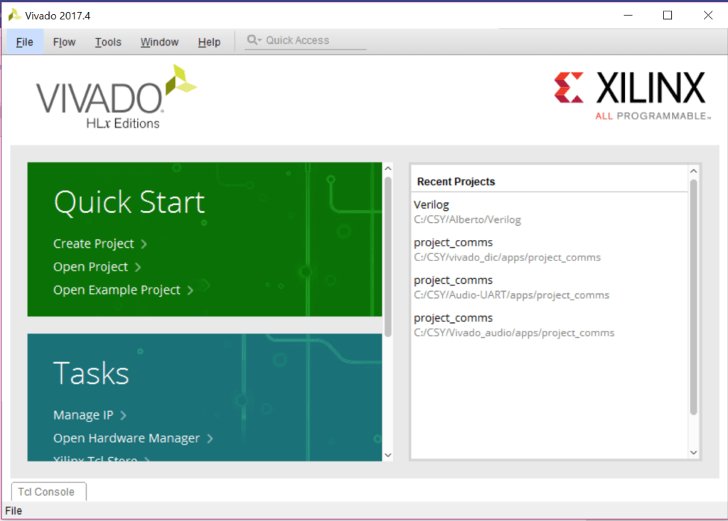
New Vivado Project
Create a new project with the assistant with File>>New Project…

Give a name and a project directory to store all the related files. In this example, I chose C:// as project location.

The type of the project should be an RTL project. If you start an empty project, you don't have any source to add to the project, therefore check the box "Do not specify at this time".
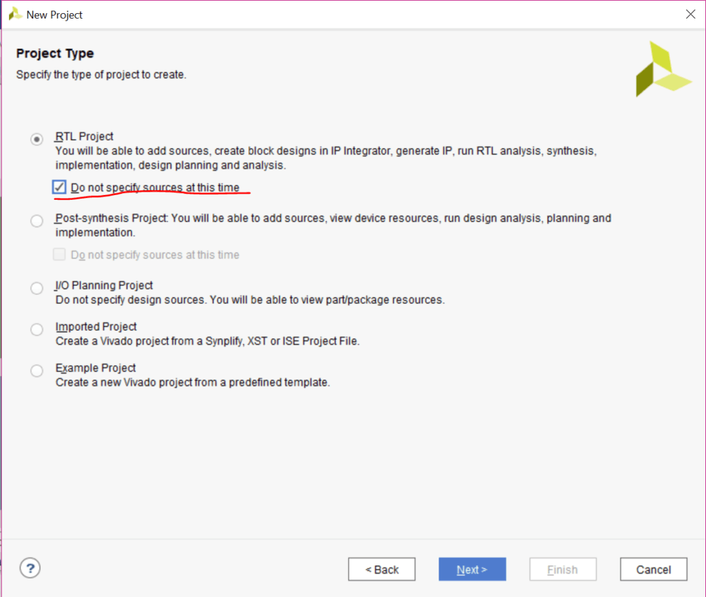
As we want to only simulate, we are not going to select any hardware. If desired this can be chosen later.

Click "Finish" and the new project will be opened.

Vivado Dashboard
The Vivado dashboard is now opened. You will get familiar with each window, when you spend some time in Vivado. For small laptop screens (as mine), it is a bit awkward to show all the information and work comfortably. You will want to maximize temporally the windows, especially the block diagram.
The fast way is to double click on the top bar of each window to maximize it (where the red crosses are) also the maximize button works identically. But I would suggest connecting a second screen to work more efficiently.

Start by creating a new block diagram to be the top of the testbench. On this diagram, all your modules are going to be placed and tested.
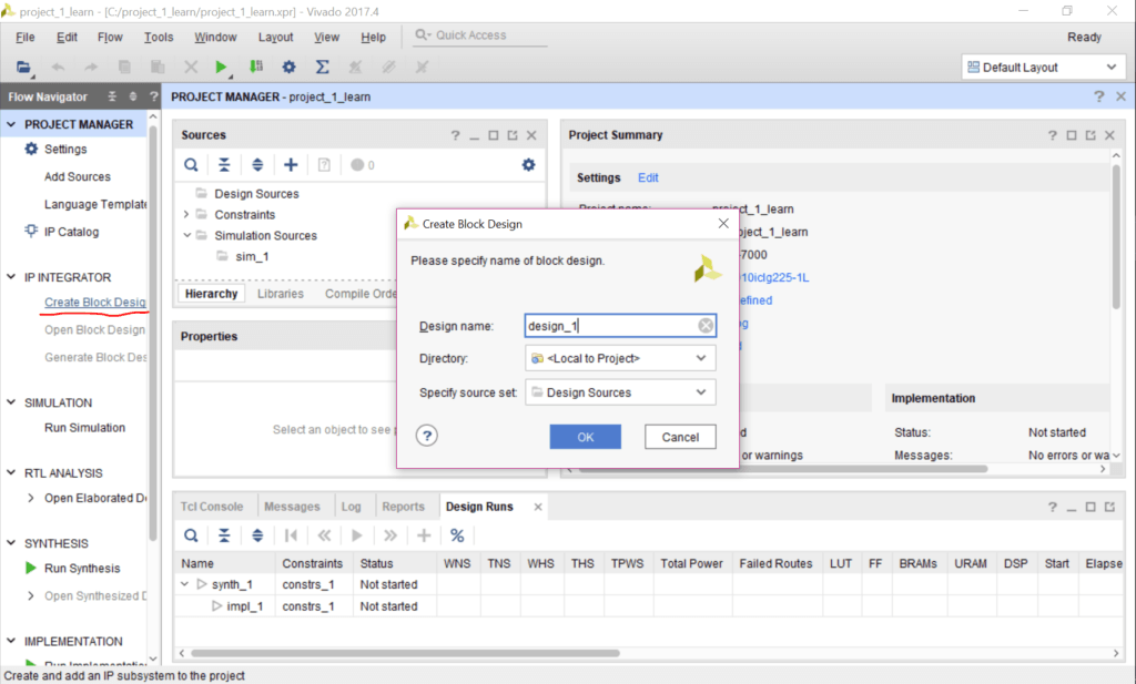
The new block diagram is now created:
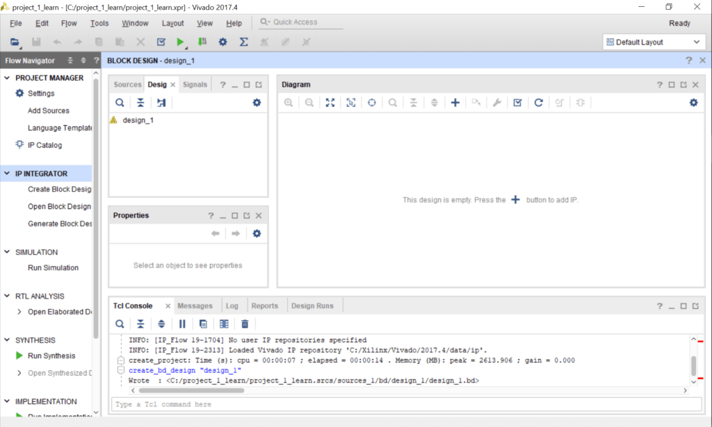
Click on "Add sources" to create the modules:

Click on "Create File":

Give a name to the RTL module, select Verilog as file type and then press OK and then Finish. 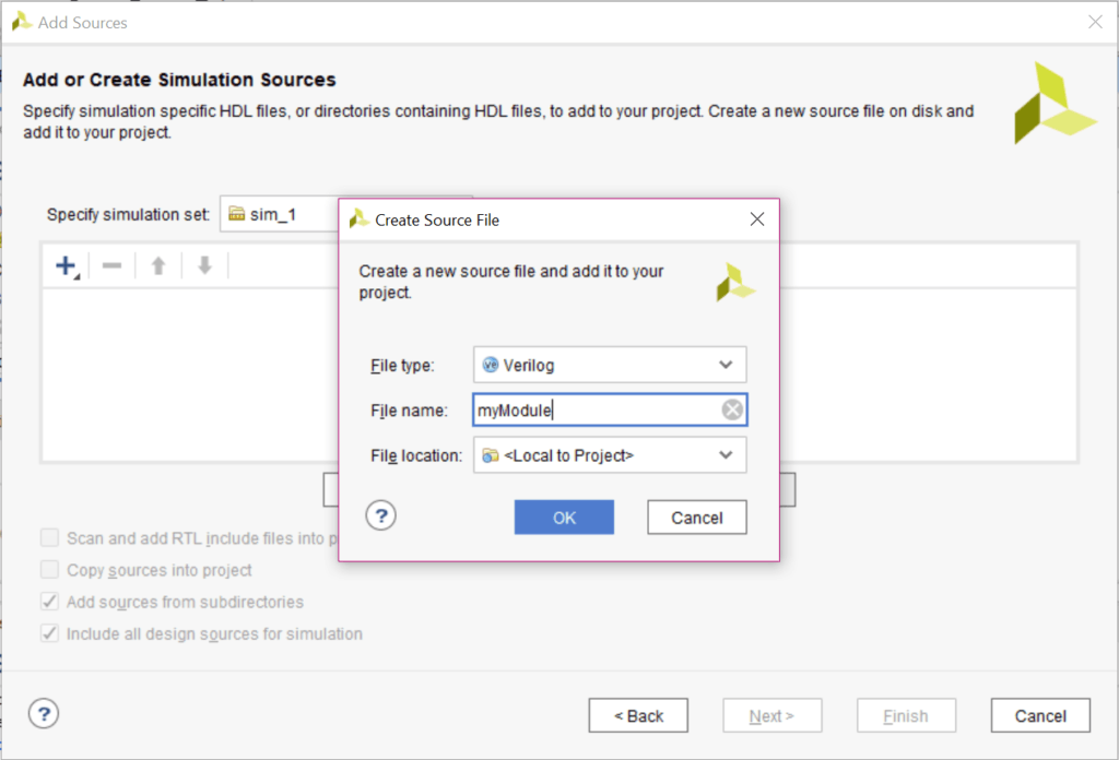
Vivado will ask you to configure the inputs and outputs. But this can be done later by code (faster and easier), so for now we skip this step pressing OK.

And when a new window is prompted, press Yes, we are sure!

Now, we are going to add some code in the module. By double click on the sources, a window will open.

There you can start typing your code. The automatic template for an RTL module in Vivado has a very big header. I hate it. You can remove it or leave it smaller as I did.

In this example I wrote a simply asynchronous and-gate in Verilog:

`timescale 1ns / 1ps module myModule(A, B, result); input A; input B; output result; assign result A & B; endmodule
For the simulation, a stimuli block or wave generator will be needed to stimulate your modules under test, in this example the and-gate. For this a new module named "Stimuli" as before is created.
`timescale 1ns / 1ps module FlipFlop( D, clk, Q); input D; input clk; output Q; reg r_FF; always @ (posedge clk) begin r_FF <= D; end assign Q = r_FF; endmodule
The following example of Stimuli can be copied as a reference:
`timescale 1ns / 1ps module Stimuli( A, B, clk); output A; output B; output reg clk; always begin clk = 1'b1; #5; clk = 1'b0; #5; // 10ns period end initial begin begin A = $urandom_range(0,1); //random value between 0 and 1 B = 1'b0; #10 //wait 10 nanosecons B = 1'b1; #30 A = 1'b0; B = $urandom_range(0,1); //to be continued... end endmodule
The created modules should be added to the block diagram to interconnect them. For that right-click on the diagram and then select "Add Module…"

Both modules can be added.

And then, we can connect the blocks with each other, just wiring the signals.

To be able to simulate, Vivado needs a Wrapper over the block diagram. This wrapper is a file that connects the output/input port of your block diagram to the physical pin described in the constraint file. In this case, we don't have yet a constrain file, but Vivado requests it.
For that we create an HDL Wrapper by right click on the block diagram sources:

Then we choose "Let Vivado manage the wrapper…"

After the wrapper is created, we to need to say to Vivado which file is our top level. This is made in Simulation settings… Right-click on the word "SIMULATION".

The setting should be checked and changed.

Now everything should be ready for our first simulation! We click on the left panel on "Run simulation" and the simulation view will open.

The signal to be plotted should be dragged into the wave diagram to see them. After that, we can click on run for a finite among of time, in this case, 120 ns. To fit the time-scale you can press the on the symbol ![]() .
.

These are the basic steps to start a simulation of your own RTL modules in Vivado. Now you should be able to simulate Verilog modules to compile and test them.
Vivado is complex, so be patient and persistent!
How To Create Testbench In Xilinx
Source: https://miscircuitos.com/how-to-create-a-testbench-in-vivado-to-learn-verilog-or-vhdl/
Posted by: suttonyoughtley.blogspot.com
0 Response to "How To Create Testbench In Xilinx"
Post a Comment